It got pretty cold this week in Southern Louisiana. I guess I should say that it is all relative but it was down in the mid to high 30’s overnight. We have been running the heaters on the boat a little bit the last month or so, but not much, just enough to take the chill out of the air. On this cold night however you can assume that both heaters were running pretty hard meaning they were not shutting off much.
In the middle of the night (about 2:30am) I heard Deb calling me saying “Hey honey, I smell something burning” I was still in a bit of a deep sleep daze but jumped out of bed and was sniffing all around the boat like some kind of a dog sniffing every thing. I just couldn’t smell anything. Deb said it seemed stronger by the navigation station but neither of us could pin point it. We made sure was all ok and went back to sleep.
About 5 am or so, I heard the heater kick off and the boat was fairly quiet (no motors, fans or pumps running for the heating units) so I just assumed that it kicked the breaker. Here is where I will blame my sleepiness because I didn’t put 2 and 2 together from the smell in the middle of the night. Duh!
 When I got up, I noticed that the breaker for the heaters was NOT off but both were without power. I turned off the power to everything and realized that I needed to have a better understanding of where the power actually comes into this boat and where it goes. Let me elaborate a bit on this.
We have two 30 amp circuits and shore power cords that come onto the boat. We have a pretty good amount of power consumption on board a 51 foot boat with 2 reverse cycle heat pump and air conditioners, electric refrigeration and water heater. we have a spare small freezer that runs on AC power as well plus all outlets on the boat. (with TV’s in each stateroom and a pretty good draw on power for a boat with 2 adults and 2 kids on board)
| I really needed to see where these went because I wasn’t sure if these 2 lines combined down below for a 50 amp power panel or something else was happening. Add to that complexity that there is a 8KW generator on board and a 3500 watt inverter. I only know the process that the previous owner and broker shared related to what breakers to flip to which position for running the air conditioners off of the generator. So that mean time for a bit of detective work.
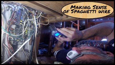
I used a tone generator connected to the 30 amp shore power inlet plugs in the cockpit and then at the other end “toned them out” to determine where each one went. I have an inexpensive tone generator that i bought a few years ago knowing that some day we would need to do some wire exploring on this boat. That day was today :). |
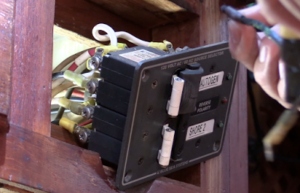
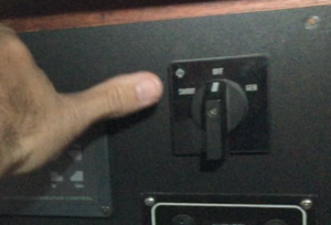
We have one 30 am shore power inlet that goes directly to a small panel with a double poled breaker that runs both heat/air conditioner units and their corresponding circulation pumps. Lets call that shore power 2 for now. We also have one line that goes directly into the rotary Shore/Off/Generator switch on the panel. We will call that Shore 1. When in the Shore Power position, it direct the power to the main AC panel (that has all the breakers for outlets, water heater, refrigeration, etc on it.)
 Here is where it gets odd and I still need to dig into it some more. The “Generator” side of the rotary switch goes to inverter, and the actual generator seems to the lockout slide selector for running the air conditioner/heater and pumps. This is a slide out breaker that won’t allow you to have it turned on for generator and shore power, it has to be one of the other. I digress and certainly have more work to understand how all that is connected and more importantly how it should be connected. Everything about this project let me to further cement the fact that the electrical needs a complete re-design and rebuild. New Panel, new wires, new runs, the whole bit. I think the previous owner had come to the same conclusion because in with all the parts that we received from him were about a dozen or so terminal blocks for a new distribution panel.
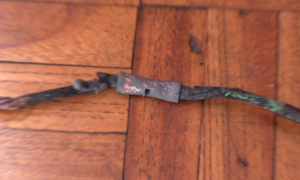
 So back to the burning smell. The hot leg of shore power 2 goes to the breaker on the heat/air conditioner panel. From the other side of the breaker it goes to a distribution bus where the runs go out to the actual units themselves. The wire burned right in half between the breaker and the bus.
At this time I was not sure if the compressor or something was drawing too many amps and that is what caused this or if there was another problem. In looking at the wires closely, I believe the issue was 2 fold. The distribution buss was rusted and the screws loose and corroded. I also found a non marine butt splice used to connect 2 strands of wire on this shore 1 foot run of wire.
At this stage I suspected that the loose and rusted connection was causing additional resistance on the line and the additional draw was just more than the thin wire (AWG 14) could handle. My plan was to replace this section of wire with AWG 10 thickness and correct marine terminals and connections but to make sure that this was not still a problem we may face, I also wanted to make sure that the line was not heating up more than it should.
| I used an infra-red thermometer to test the temperature of the wire and breaker and connections before power was applied. I then ran all units (Air and Heat both) and continued to monitor the temperature to be sure that they were not getting hot. It never went above 84 degrees Fahrenheit on the wire itself (from 73 or so without power). That was my way of validating all was correct.
At this point, this was really a patch job. I need to trace, and redesign the entire system. I noticed that the DC ground was connected to the AC ground. I didn’t see a separate neutral and ground buss isolated for the generator versus shore power or even the inverter so I do really believe that this is a challenge of building a mansion one room at a time. We need to start with a fresh blueprint for the power on this boat.. |
I used the correct wire, the correct connections and while it felt good to do that, it does not solve the issue that I still face and that is that the rest of the system needs to be done according to ABYC standards (This is the American Boat and Yacht Council guidelines that govern safe boat building techniques in the United States)

